Extend the tuning ability of the Yaesu FC-40 auto-tuner.
Build a simple broadband transformer that greatly extends the range of antennas that can be matched.
September 2005
ARRL Antenna Book 19th edition, chapter 26-15 "Coupling the line to the antenna, Broadband Matching Transformers."
|
|
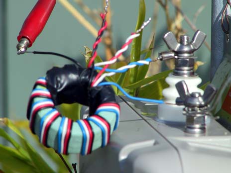
The toroid
The toroid is a standard HF ferrite toroid commonly used for balun construction. Because the FC-40 is limited to 100 watts, the toroid only needs to be modest, mine was 40mm in diameter. See your ARRL for more info about types of ferrite if you are in doubt.
The windings
I wound mine using copper telephone wire stripped from the slightly heavier duty black cable that goes from your house to the pole; the colours help make the connections easier but any insulated single conductor light copper wire will do.
Wind 4 strands of wire together neatly alongside each other as illustrated above as if they were a single wide wire.
Wind a total of twelve turns (10 to 14 turns is fine).
After winding the 12 turns, connect the end of each wire to the beginning of the next.
Eg. the single blue wire is the "start" (point 1 on the ARRL diagram). The "end" of that blue wire is connected to the start of the white (point 2/3 on the ARRL diagram). The end of the white is connected to the start of the red, and so on. The remaining black single wire is the end of the last of the four wires (point 8 on the ARRL diagram).
Connecting the transformer
The primary of the transformer connects to the ATU. The start of the light blue wire *must* go to ground - meaning the ground terminal on the ATU as well as the real ground. You can just see my silvery out of focus wire connected to the ground of the ATU which goes to an earth stake.
The blue/white is other end of the primary and goes to the active terminal of the ATU.
The secondary connects to the antenna and which tap you use depends on the impedance of your antenna. You can see in the photo a red alligator clip connected to the end of the antenna, 100m or so of aluminium welding wire. It just happens that my wire antenna works best at 16:1
By the way, most toroids do not work above 30MHz so don't expect to get on 6m with it.
The red/white termination is 4:1 (ie. 4 x 50 ohms = 200 ohms)
The red/black termination is 9:1 (ie. 9 x 50 ohms = 450 ohms)
The single black wire is 16:1 (ie. 16 x 50 ohms = 800 ohms)
Connecting it backwards
The transformer will step down instead of up if connected back to front. To use it that way the single light blue wire still connects to ground as in the photo above (meaning the real ground or car chassis ground and the ATU ground terminal) while the antenna feedpoint connects to the point 2/3 which in my case is the blue/white wire junction.
The active ATU terminal then connects to whichever of the other terminations works best. Eg. the single black wire would step your coax 50 ohms down by 16:1 to just 3 ohms, while the red/black termination would step it down to 5 ohms, etc.
Short verticals have very low impedances. For example a 12 foot whip on 80 meters has a radiation resisitance of less than one ohm. In practice the return loss of the ground for a mobile may be something like 10 to 20 ohms. This is effectively in series with the whip giving a combined higher impedance as seen by the ATU.
73