|
Wire and trimmer capacitors |
|
1. Wire : Do you want to use different wire?
You can use thicker wire or wire with thicker insulation but it complicates things. It can be compensated for during the first stage of construction which is building the centre loading coil and getting the squid pole resonant on 40m, specifically 7.1MHz. BUT you have to have access to an antenna analyser or at least a grid dip oscillator to measure the resonant frequency exactly. Checking the SWR will NOT give you the exact resonant point as the resonant point does not give lowest SWR. If you have thicker wire these are the steps I suggest: - use 10.2m wire length and add an extra 2 turns to the existing 7 turns on the centre loading coil, making it 9 turns total. (It might seem counter-intuitive that you need extra turns if the wire is thicker, but that is because the turns are forced further apart from each other by the thicker wire and/or the thicker insulation and this lessens the coupling between turns and reduces the inductance.) It is really important to achieve resonance at 7.1MHz before you proceed with the rest of construction. The reason is that 20m is exactly twice that frequency and 15m is exactly three time that frequency, so any error will be doubled and tripled! On 20m you want resonance at 14.2Mhz and on 15m you want resonance at 21.3MHz. Thinner wire is not recommended because it's too flimsy but if you want to persist then go ahead and measure the resonant frequency and adjust the centre loading coil until you get it right on 7.1MHz
1mm enamelled wire is usually available from Dick Smith on small spools, from some speaker inductors sold at Jaycar, and from electric motor rewinding businesses. Electric motor rewinding businesses are a good source and usually sell it cheaply by the meter. Sometimes old power or speaker transformers have the right diameter. You will need about 5 meters of enamelled wire in total.
I've received feedback from England that their PVC is 40mm but that's not different enough to break the design. Several local constructors here have used different diameters, Peter VK7KPC used a much smaller diameter former so that he could put it inside the squid pole; he used MMANA to calculate the required inductance and position on the wire, and has it working well. Joe VK7JG mounted his 20m coil on a former on the end of a piece of Heliax and got it going first try... It's beyond the scope of my article to cater for anything other than the 42mm common garden variety I used (you can find bits of it on building sites all over the country). Feel free to play and let me know how you go! |
|
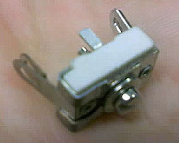
3. Trimmer capacitors : What types are there and what are the limits? a) Below are a couple of typical mica compression trimmer capacitors. They work well for this project. Unfortunately many in junk boxes have too high a value which makes them too hard to tune. The range you need is from 5pF to a maximum of 25pF.
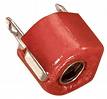
b) Below are several beehive trimmers. Again, they work well. Make sure they cover the range up to 25pF or 33pF maximum.
c) Below is what plastic or Teflon trimmers look like. They also work well. Same comments apply to the desirable maximum 25pF
d) The small coloured ceramic trimmers as shown below are generally not suitable for 100 watts as they have too low a break down voltage. They come in a variety of colours, depending on value.
|


|
Tuning and problem solving |
|
Problem: I can't seem to find resonance, resonance is not obvious, resonance is 'fuzzy' and 'broad' You are probably experiencing those problems because you have a poor ground system. This is especially true of 80m. In order to tune the squid pole (and operate it!) you do need a reasonable ground of some sort. I use my truck, or where the squid pole is attached to a post or star dropper, I use four tape measures of 5 to 8m long as radials; that is the absolute bare minimum and may still not be enough. |
|
Problem: Resonance on 40m or 20m seems "stuck" and doesn't change when I tune the trimmer or change the turns on the coil You probably have tuned radials or attached the pole to something that is accidentally resonant on the band in question thus swamping the measuments. If you have carefully cut 1/4 wavelength radials for use on 20m or 40m then they are probably the culprit. This can happen accidentally, as you may have mounted your squid pole on some structure that is accidentally resonant at or near one of the bands of interest. The effect of tuned radials can be very marked and can swamp the measurement of resonance of the squid pole itself. For example if your radials were accidentally tuned to (say) exactly 14.5MHz, then they would have such a large influence on the tuning of the whole antenna system that despite any adjustments you made to the actual squid pole wire or it's 20m trimmer, it could still show up as resonant on 14.5MHz. You will be much better off with radials that are not anywhere close to 1/4 wave at all of the frequencies in use. If you think that's happening to you, try mounting your squiddy temporarily on some other ground system and measuring it again. |
|
Problem: I can't seem to get the 80m coil tuned to 3.6MHz Almost all the problems on 80m are caused by a poor ground plane. Remember that the real ground is NOT a ground plane, real ground is a very poor conductor and absorbs much of your signal - and that does not change no matter how many fantastic metal earth stakes you drive into it. The performance limitations on 80m (and to a slightly lesser extent on 40m) are ground losses. That is the case for all vertical antennas. If you plan to use it seriously on 80m, then you might consider a pair of nice long 80m radials in addition to your normal ground. The good news is that you can get more and more performance out of any vertical by improving your ground system! If you have access to an antenna analyser or grid dip oscillator, then here is the way to troubleshoot your 80m coil: - wind the 80m coil primary to my specifications The idea is to temporarily connect up the 80m coil in series with the squid pole (ie. use it as a simple loading coil at the base of the pole) and then measure it's resonant frequency using whatever equipment you have. Adjust the number of turns to achieve resonance at 3.5MHz. Winding the secondary on will raise the frequency slightly. Remember, it is easy to spread the windings apart a little to raise it to resonance on 3.6MHz, it's much harder to add on an extra turn of wire! If you don't have access to any test gear then try adjusting the coil as described above for lowest SWR. Use low power on 3.5MHz. When you have it resonant on 3.5MHz, then go ahead and wind the 5 secondary turns, and connect it as per the construction details. |
|
Problem: I can't seem to get a good 50 ohm match on 20m or 80m If you find it's close enough and you are sick of fiddling with it then maybe just use an ATU! On the other hand, with care and a little effort it is certainly possible to get a perfect 50 ohm match on 20 and 80. Here is an outline of what you are trying to achieve: a. 40m: Get the squid pole with centre loading coil resonant and working with a 1:1 (or very close) SWR on 7.1MHz when mounted over a good ground. Do not proceed with any other construction until you've achieve that because if you go back and change things on 40m it will throw all your other work out the window. It will not stay perfect across the band of course but you should expect to achieve better than 1:1.5 SWR from 7.0MHz to 7.4MHz. b. 20m: Build the 20m tuned circuit complete with secondary coil. If you have a GDO or antenna analyser, you can check the 20m tuned circuit for nice clean sharp resonance on 14.2MHz before you attach it to the squid pole wire. If you have no test instruments, then connect the 20m coil to the squid pole wire, as for normal use. Using your SWR meter and transmitting on minimum power on 14.2MHz, slowly adjust the trimmer and watch for a nice dip in the SWR at some point. Even if the dip does not go to zero, the SWR dip should be nice and obvious and smooth at some point. If your trimmer capacitor is too high in value, you will probably see a small dip occur at the trimmer minimum value. You could take off a turn of enamelled wire from the 20m coil and try again, otherwise you will need to find a trimmer that is capable of a lower minimum value. If the dip occurs at a reasonable spot on your trimmer (halfway would be perfect) but you still can't get the SWR perfect, then you need to adjust the secondary turns on the 20m coil. Loosen the insulation tape on the 2 turn secondary winding, and try moving those two turns either down slightly off the bottom of the primary, or slightly above the bottom of the primary and trying again. You might try spreading those 2 turns apart a little. You will need to remove your hand and re-tape it temporarily to test it, as your hand will stuff the measurements. If you have an antenna analyser you can see exactly what effect moving the secondary has, and by playing around achieve exactly 50 ohms non-reactive. It will not stay perfect across the band of course but you should expect to achieve better than 1:1.5 SWR from 14.0MHz to 14.35MHz. c. 80m: Assuming you have achieved resonance at the target frequency of 3.5MHz by using the 80m coil (minus secondary) as a simple base loading coil, then you can wind on the secondary. The way to get a perfect 50 ohm match is by trial and error, as described on 20m above. Move the start of the 5 turns slightly below the enable winding, or spread the turns apart a little, or remove a turn. If you can measure the results on an antenna analyser you can achieve a perfect 50 ohm match. It will not stay perfect across the band of course but you should expect to achieve better than 1:1.5 SWR from 3.5MHz to 3.7MHz. |
|
Question: Does it matter how I wind the wire up the squid pole? Nope! The helical winding of the wire up the squid pole is simply so that a) the wire stays on the pole without having to be taped to it and b) the wire is as long as possible so that the centre loading coil inductance can be as small as possible. Just wind it evenly and neatly as per the photo of the squid pole at the top of the previous page. The helical turns on the squid pole do not have any effect like a "coil" because their spacing is too great. The inter-capacitive coupling between their "turns" is effectively zero, and inter-capacitive coupling between turns it what makes a coil have inductance. Think of a capacitor: the plates have negligible capacitive effect unless they are very close together. |
|
Question: Should I have resonant radials, do they help? Nope! Radials do not need to be 1/4 wave long, especially on HF and close to the ground; according to Cebik the effect of the ground being so close nullifies any real benefit from making them longer than something like 0.2 of a wavelength. Unless you install dozens of radials of course, which would be ideal... If you have the space and inclination you might make them about 0.15 of a wavelength long on 40m. That's about 6m long, so you can see that 8m tape measures would be fine as an all-round compromise. One problem with "tuned" radials is that they can swamp the effective resonant frequency of the squid pole as described in the "my squid pole resonance seems stuck" problem above. |
Page 1 < back to description and construction details