|
Fancy a cheap, collapsible self-contained portable antenna for 80, 40, 30, 20 and 15m that works really well and can be erected in minutes? The inexpensive 9m long ultra-light telescopic fishing pole known in Australia as the squid pole makes a good antenna. Motor-home mobile round Australia gave me time to model every portable antenna I could think of using MMANA modelling software, plus test them in the field. Travelling Australia and camping outdoors for eight months at a time provides strong motivation to build and improve antenna systems capable of reliable scheds with mates back home. The squid pole retailing as the Telepole 900 sells for ~$50 from Tamar Marine in Launceston [Note** at page bottom for latest supplier info.], it consists of 9 sections each a bit longer than 1m, extending to a full 9m. It is self supporting even in a brisk breeze and easily mounts in a short section of 50mm PVC similar to a surf fishing rod holder. Most surf rod holders are too narrow to accommodate the base of the 47 mm diameter Telepoles. Squid poles are thin and flexible at the top and can't support the weight of even a light dipole or G5RV so the pole is used as a support for a vertical wire wound along its length as per the photo on the left. The squid pole as an antenna• winding a length of light insulated wire helically around the pole as you slowly extend it is the easiest way of attaching a wire for use as an antenna. |
 Introducing the squid pole
|
The construction details below optimise the antenna for use on 80, 40 and 20m. It also radiates well on 30 and 15m. |
On 80m the squid pole is a bottom loaded quarter wave. An 80m vertical provides low angle radiation (around 20 degrees) making it better than my portable G5RV for long distance contacts, e.g. up to 3,700 km regular scheds from the WA coast and Cape York to Tasmania. It's not as good as the G5RV for the usual local rag-chews, as the G5RV radiates straight up at 90 degrees providing high angle sky wave that bounces back down locally - good for short comms. An 80m vertical provides low angle radiation (around 20 degrees) making it better than my portable G5RV for long distance contacts, e.g. up to 3,700 km regular scheds from the WA coast and Cape York to Tasmania. It's not as good as the G5RV for the usual local rag-chews, as the G5RV radiates straight up at 90 degrees providing high angle sky wave that bounces back down locally - good for short comms.
A low-loss 25 turn loading coil with a 5 turn secondary winding provides a near 50 ohm feed point on 80m. MMANA modelling shows a radiation resistance of about 5 ohms which makes the 9m long squid pole a very much more efficient antenna than a typical short HF whip. For example a typical 1.5m long whip on 80m has a radiation resistance of just 0.1 ohms; that's right , one tenth of an ohm! That means if the ohmic resistance of the loading coil wire and associated connectors is (typically) 2 ohms, more than 95% of your transmitter power is NOT radiated and simply turned into heat by that resistance. In addition: (a) people tend to overlook the fact that a coil does NOT radiate - so with a typical 80m whip the only part that radiates is the stinger adjusting rod at the very top. (b) because most radiation occurs from the high current bottom section of a quarter wave vertical, you are replacing the most important and effective part of your antenna with a non-radiating inductance. |
On 20m the squid pole is an end-fed halfwave. On 20m a parallel tuned circuit matches the high impedance of the 20m end-fed halfwave and the 2 turn secondary winding provides a near 50 ohm feed point. The trimmer is tuned for resonance at 14.2MHz On 20m a parallel tuned circuit matches the high impedance of the 20m end-fed halfwave and the 2 turn secondary winding provides a near 50 ohm feed point. The trimmer is tuned for resonance at 14.2MHz The end-fed half wave squid pole is 'ground independent' with an elevated high current radiation point providing excellent low angle radiation; you'd need a Yagi or a curtain or 4-square array to beat it. The trimmer capacitor is easily adjusted for a flat SWR into a 50 ohm load so it works with no ATU. Using the squid pole on other bands: The radiating wire with centre coil is directly fed at its bottom end on all other bands via an ATU. On 40m, because of the centre loading coil, the antenna is a full quarter wave resonant at about 7.1MHz. MMANA modelling shows the radiation resistance is about 25 ohms which together with the series ground return losses (depending on how bad your ground is) brings the feed point impedance up to about 40 ohms. Performance on 40m is excellent with good low angle radiation. On 30m the antenna also has a good low angle radiation pattern. It is not resonant, but that does not affect any antennas ability to radiate - it just means an ATU is required. On 15m the antenna is resonant at 21.3MHz which is the 3rd harmonic of 7.1MHz so an ATU can easily match the ~200ohms non-reactive feed point impedance. |
|
Parts required 12 meters of insulated multi-strand copper hookup wire; the copper inner is 1mm in diameter. This wire is strong and flexible and not too heavy. It is used as the radiator and for the secondary windings on the 80 and 20m coils. Short lengths are also used to connect the coils to the ATU. 5 meters of enamel copper wire approx 1mm diameter. Diameters smaller than 0.7mm need a couple *fewer* turns and greater than 1.2mm need a couple *more* turns. That might sound counter-intuitive but it is caused by the inter-turn coupling which reduces as the wire gets thicker. 150 mm of 42mm outside diameter PVC pipe. This is used for the coil formers. Other diameters and materials will change the calculations so please stick to 42mm PVC. 3 x chassis mount banana sockets, 4 x banana plugs. 1 x 25pF mica compression trimmer capacitor. A small bee-hive concentric trimmer will also work OK. (See † footnote) A roll of good insulation tape. A short length of thin nylon strap or cord. A small diameter plastic rawl plug that is a firm push-on / pull-off fit on the tip of your squid pole, or a fishing swivel with a safety-pin style clip. A self adhesive Velcro patch. |
|
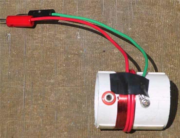
Construction details Below: The Velcro holds the radiating wire at the bottom of the pole. The black taped over nylon strap on the right of the illustration is a sort of buffer/collar that helps prevent the bottom end of the squid pole from rattling round inside the PVC 'fishing rod' holder. Because the squid pole is tapered and has a slightly larger diameter screw end on the bottom, a layer of nylon strap or cord needs to be wrapped around the pole about 20cm from the bottom. This helps provide a snug fit for the pole base in the 50mm PVC holder. I roll up my radiator wire on a cheap plastic fishing line hand reel for storage. |
 The Velcro patch on the left of the illustration is a simple way of holding the radiating wire captive to stop it unwinding. The top Velcro layer lifts back to release the wire.
|
Below: The rawl plug holds the radiating wire at the top of the pole. NOTE: Some constructors tell me they used a fishing swivel to clip onto the tiny eyelet on the top of the squid pole and I think that is a superior method to my original system. |
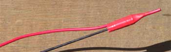 A small diameter rawl plug is used to slide firmly over the top of the squid pole after the tiny wire loop at the top of the squid pole is cut off.
|
Below: The 7 turn centre loading coil* is integrated into the radiating wire. 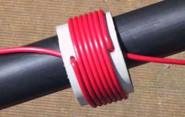 1. Cut the radiating wire to a length of 10.1m. This includes the wire for the coil. 1. Cut the radiating wire to a length of 10.1m. This includes the wire for the coil.
2. Cut a 30 mm length of 42mm diameter PVC pipe for the off-centre* coil former. 3. Wind 7 turns of the radiating wire round the PVC former, poking the wire through the holes as illustrated. 4. The resulting length of wire + coil is used as the radiating element on all bands. 5. Congratulations. Your squid pole is now ready for use on 40, 30 and 15m. |
Next we build the 80 and 20m additions.
|
Below: The 80m coil: 25 turns of 0.8mm enamelled copper 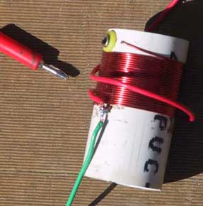 1. Cut a 70 mm length of 42mm diameter PVC pipe for the 80m coil former. 1. Cut a 70 mm length of 42mm diameter PVC pipe for the 80m coil former.2. Drill a hole close to one end of the PVC and mount one of the banana sockets in the hole with its solder tab on the inside of the PVC pipe. My banana socket is the yellow one shown on the left. 3. Drill a small hole near the banana socket for neatly feeding the enamel wire through. 4. Bare 2cm of one end of your spool of enamel copper wire, scrape the enamel off with a sharp knife and poke it through the hole in the PVC and the banana solder tab. Solder the wire to the tab. 5. Wind 25 turns of the enamel copper wire neatly and tightly onto the PVC former. 6. After winding all the turns on, cut the wire so you have about 4cm remaining. Bare the wire by scraping it carefully. 7. Drill a hole right at the bottom of the winding and poke the end of the wire through and then a second hole to bring it back out again, so it can be soldered to. 8. Solder a length of spare radiating wire to the enamel wire as per the red wire you see on the left and wind 5 turns of it over the bottom end of the enamel wire winding (look at the secondary winding on the 20m coil below to see where to place it), leaving enough spare as a tail to connect to ATU or coax. In this illustration I'm about to start winding the 5 turn secondary. 9. Solder a second 15cm length of spare radiating wire to the other two wires (my wire was green to make it easy to remember that its the earth wire). This tail will connect to the ground point on your ATU or coax. See the 20m coil below which shows the similar two tails. You can adjust the SWR by slightly repositioning the secondary turns closer to or further from the bottom of the enamel winding. When the windings are in place, cover them tightly with insulation tape. |
|
Below: The 20m coil: 10 turns of 0.8mm enamelled copper
Tuning Tune the 25pF trimmer for maximum received signal strength at 14.2MHz. Fine tune it by adjusting it for minimum SWR at low power output on the same frequency.
|
 1. Cut a 50 mm length of 42mm diameter PVC pipe for the 80m coil former.
|
Connecting to your ATU For portable use it is highly desirable to position the ATU right at the bottom of the squid pole. That way there is no coax between the ATU and the squid pole and thus no RF coming back down the coax into the portable radio shack. Stray RF with a poor earth is usually overcome when the ATU is at the base of the antenna because that configuration provides properly matched coax running back into the vehicle or tent. The perfect solution is a remote ATU and if you are doing much portable work you should rush out and buy one now. I use the Yaesu FC-400. If it is not possible to connect directly to the ATU, use as short a length of coax as conveniently possible and wire it with banana sockets and something to connect it to the nearest piece of metal at the base of the squid pole mount. On 80 and 20m the radiating wire plugs into the banana socket on that band's coil former. The active banana plug from the coil secondary winding (e.g. the red wire illustrated above) plugs directly into the SO239 socket on the back of the ATU. The fact that bananas can plug into SO239 sockets is one of the joys of banana plugs. Wire a banana socket to the earth lug on the ATU to plug in the coil earth lead. That allows simple swapping of coils by plugging them in and out. On 40, 30 and 15m the coils are not used and the radiating wire plugs directly into the ATU SO239 socket. Ground If the squid pole is not mounted on something like a car, trailer or truck that can provide at least a minimum workable ground plane, you should consider making some plug-on radials from cheap metal tape measures as mentioned above. Make them anyway, radials help with any portable installation and you can never have enough of them for any vertical. Typical ground return losses are in the vicinity of 10 to 20 ohms and this value is in series with the antenna radiation resistance. This means that the lower the frequency, the more the ground loss effects the overall efficiency. E.g. on 80m a ground loss of (say) 20 ohms in series with the 5 ohm radiation resistance would turn 75 watts of your 100 watt transmit power into heat. Radials work best away from the ground and are easily arranged so they droop from the bottom of a squid pole that's 2m or more off the ground. 4 x 5m tapes are long enough to help a lot, they are trivially easy to deploy in the field and cost as little as $2 each. A star-dropper or earth stake will NOT provide any effective ground at all. What ground you have will also effect the direction in which your antenna works best, especially on the higher frequencies. E.g. if there was a very poor ground in a northerly direction from your antenna and a good ground in a southerly direction, more of your signal would be lost in the poor ground to the north than the good ground to the south, so the antenna would work best with stations to the south of you. |
* The centre loading coil is actually placed a little lower down the squid pole than the centre, being exactly 4,700 mm from the top of the wire.
This position was calculated using MMANA modelling software to provide simultaneous resonance on 20m and 40m. The complication is because a
loading coil has maximum effect at a high current point and needs more inductance the further it moves from the high current point. On the 20m
half wave the current maximum is at the middle of the squid pole while on the 40m quarter wave the current maximum is at the bottom of the pole.
---
Note** Since writing this article Tamar Marine have run out of stock, but our local club has purchased over thirty from another source:
http://www.haverford.com.au
19 Grey Street, Carlton NSW 2218
P.O. Box 401 Kogarah NSW 1485
Phone (02) 95881777 Fax (02) 9588.4777
If you want a really long one, like a full 1/4 wave on 80m, try Spiderbeam. They also sell very strong walled 12m long versions.
† trimmer capacitors for our club project have been sourced from Rockby in Victoria, part number 35966.
It is a rectangular shaped, ceramic mica comression device, 8-40pF
---
PS. Don't try to use it on 6m because you will regret it. Even if you could, the radiation pattern is poor with very high angle lobes.
Page 2 > Trouble shooting guide and notes